MagLev Rail Starter Build Instructions
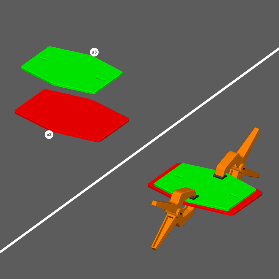
Step 1
- Glue and clamp a2 and a3 as shown to create a foot base.
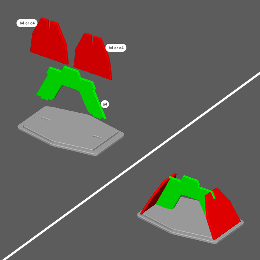
Step 2
- Glue a4 and and two of either b4 or c4 pieces to the foot base as shown to complete a foot assembly.
Note: Repeat steps 1 and 2 for all of the feet in the set. The parts b4 and c4 are interchangable.
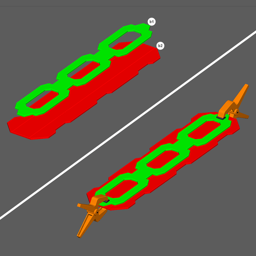
Step 3
- Glue and clamp b1 and b2 as shown to create a straight rail top assembly.
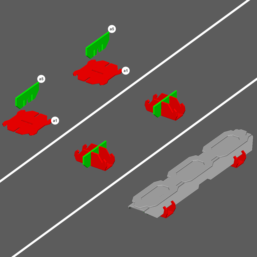
Step 4
- Glue pieces a1 and a5 as shown to create support assemblies.
- Glue both support assemblies onto the straight rail top assemblies as shown to complete a straight rail piece.
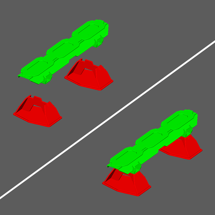
Step 5
- Insert tabs on the foot assembly into the slots on bottom side of straight rail as shown.
Note: Do Not Use Glue as these pieces are meant to be removable for storage. Repeat steps 3-5 for all of the straight rails in the set.
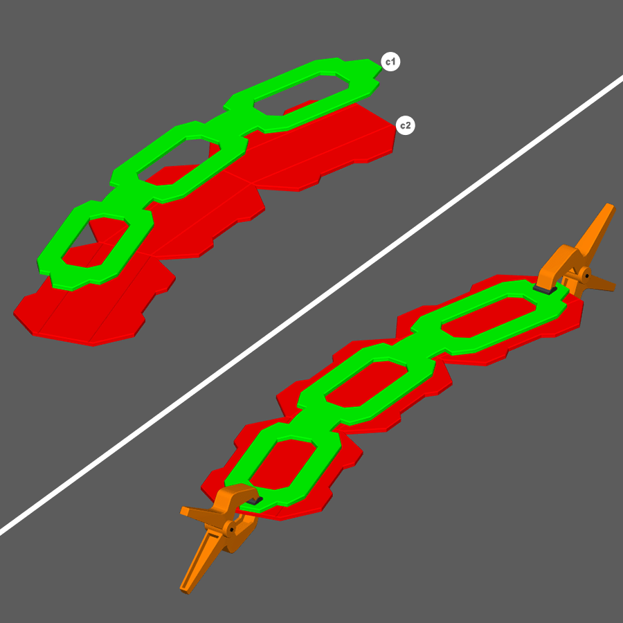
Step 6
- Glue and clamp c1 and c2 as shown to create a curved rail top assembly.
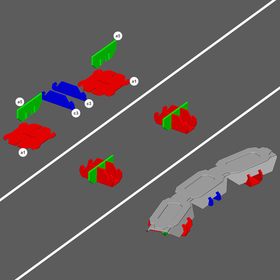
Step 7
- Glue and assemble pieces a1 and a5 as shown to create support assemblies.
- Glue both support assemblies onto the curved rail top assemblies as shown.
- Glue and assemble pieces c3 as shown to complete a curved rail piece.
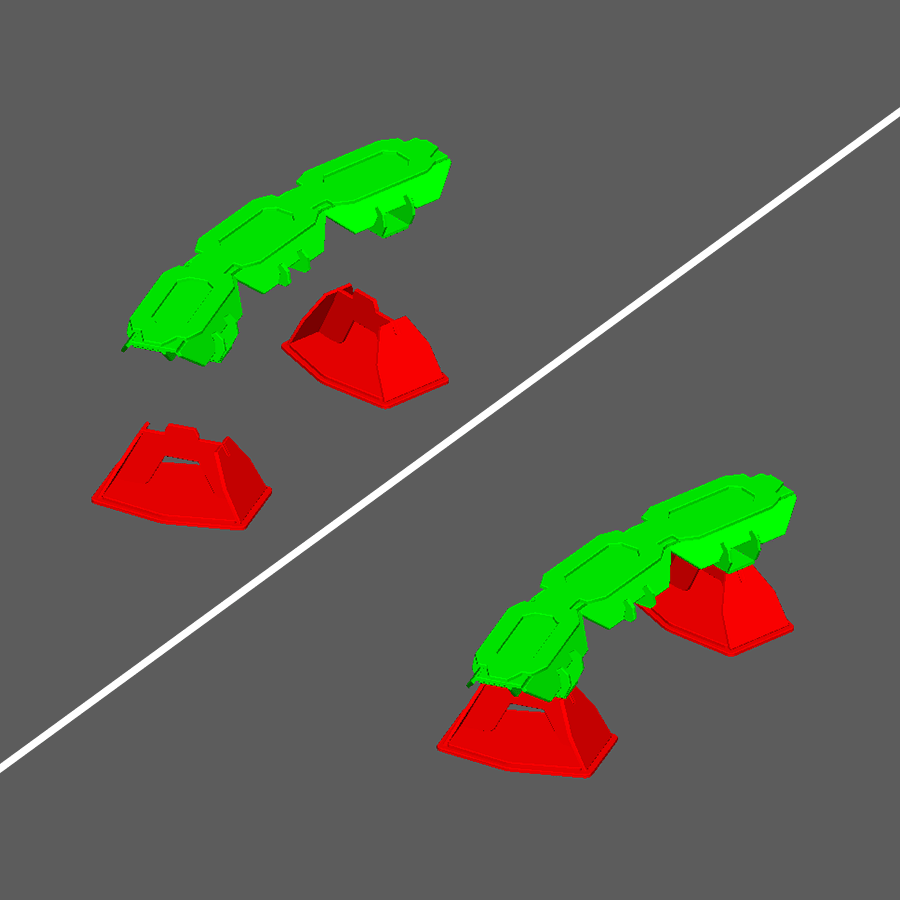
Step 8
- Insert tabs on the foot assembly into the slots on bottom side of curved rail as shown.
Note: Do Not Use Glue as these pieces are meant to be removable for storage. Repeat steps 6-8 for all of the curved rails in the set.
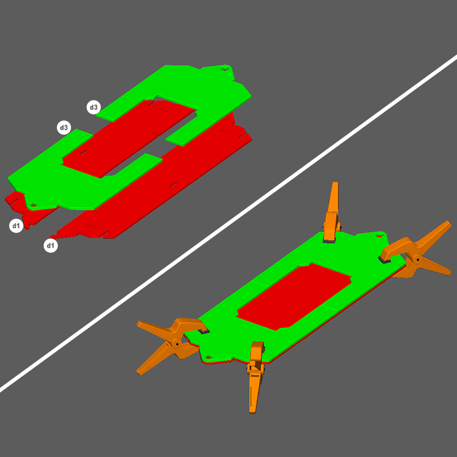
Step 9
- Glue and clamp both d1 and both d3 pieces as shown.
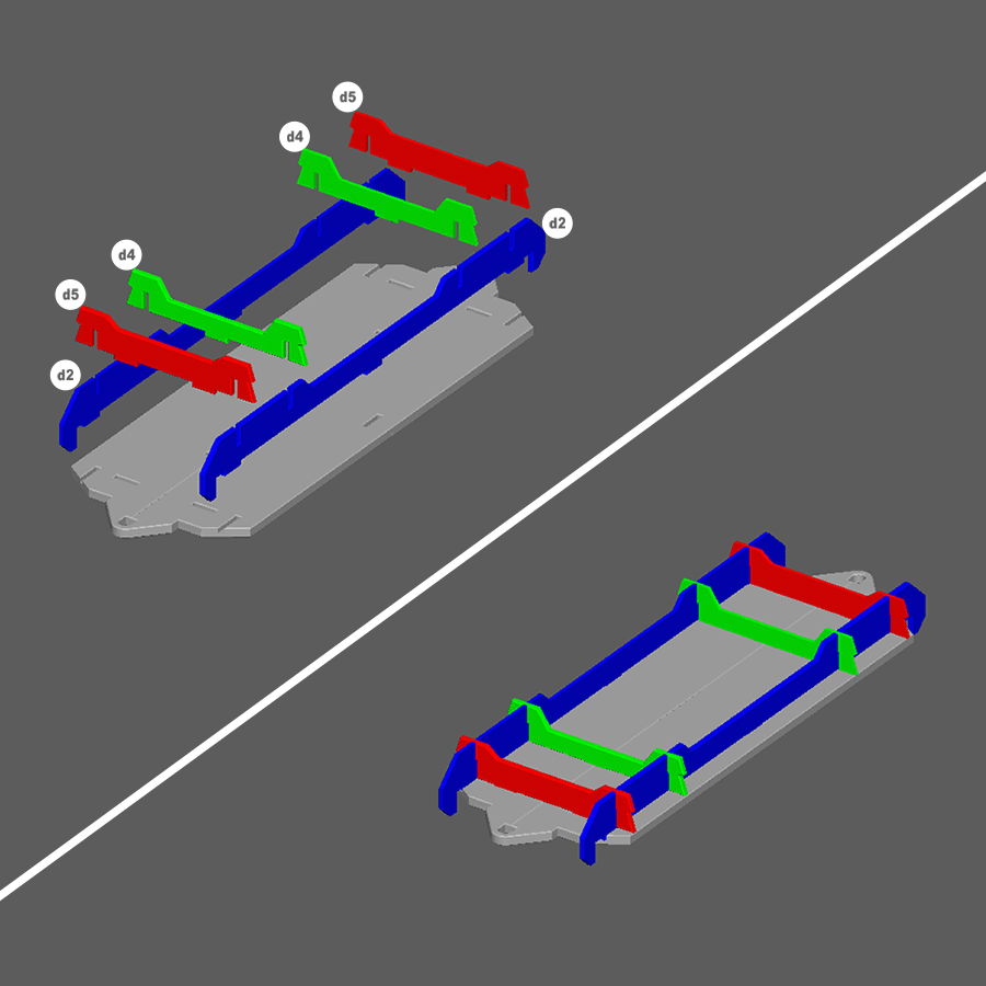
Step 10
- Glue both d2 pieces to the bed assembly as shown.
- Then glue both d4 and both d5 pieces to the bed assembly as shown to create the rail car bed assembly.
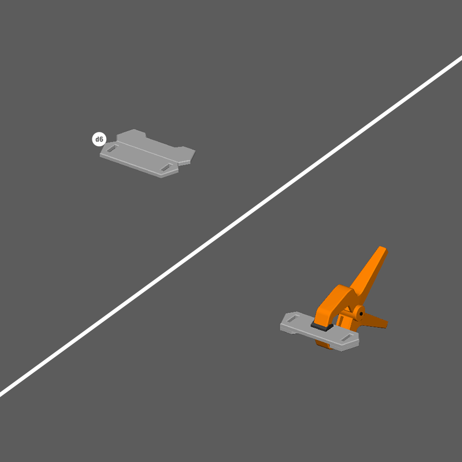
Step 11
- Glue and clamp d6 as shown to create a maglev assembly.
- Repeat 3 more times.
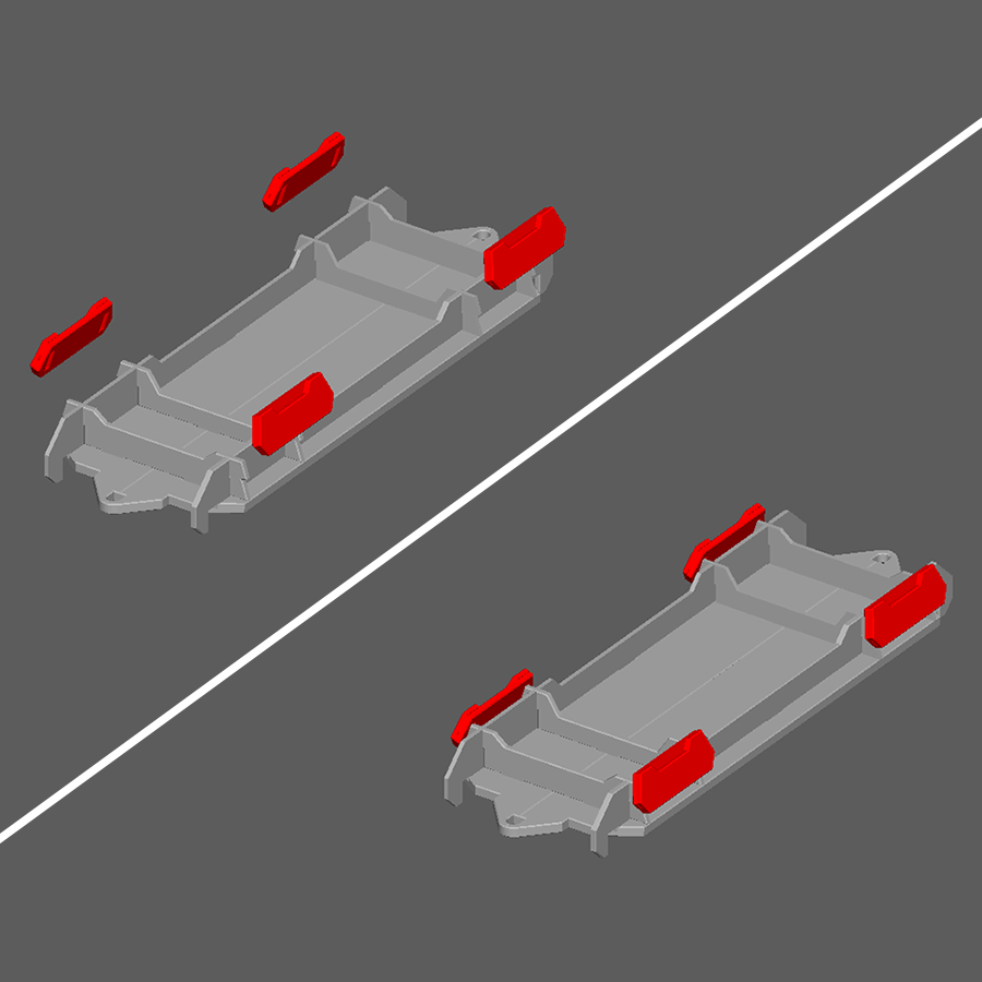
Step 12
- Glue the four maglev assemblies to the rail car bed assembly as shown.
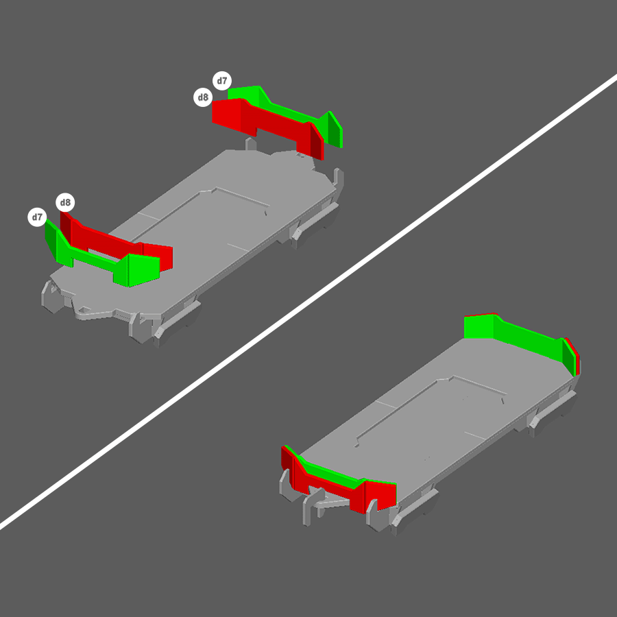
Step 13
- Glue both pieces d7 to both pieces d8 and glue onto rail car bed assembly as shown to complete the MagLev Rail Car.
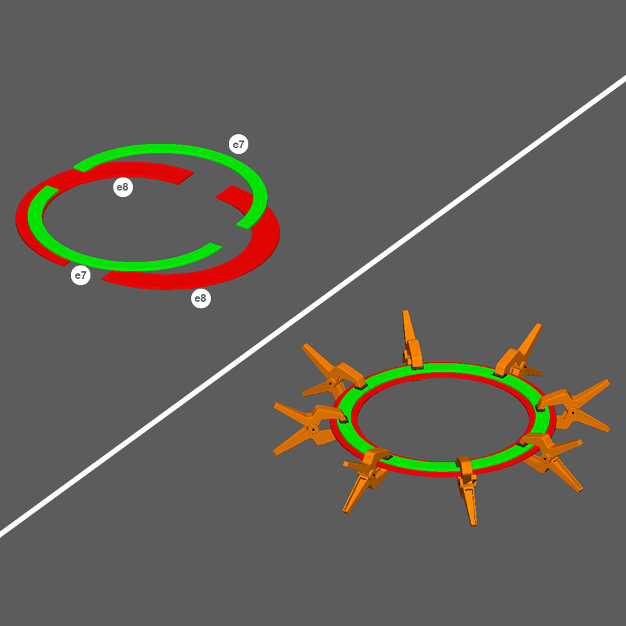
Step 14
- Glue and clamp both e7 and both e8 pieces as shown to create the switch track.
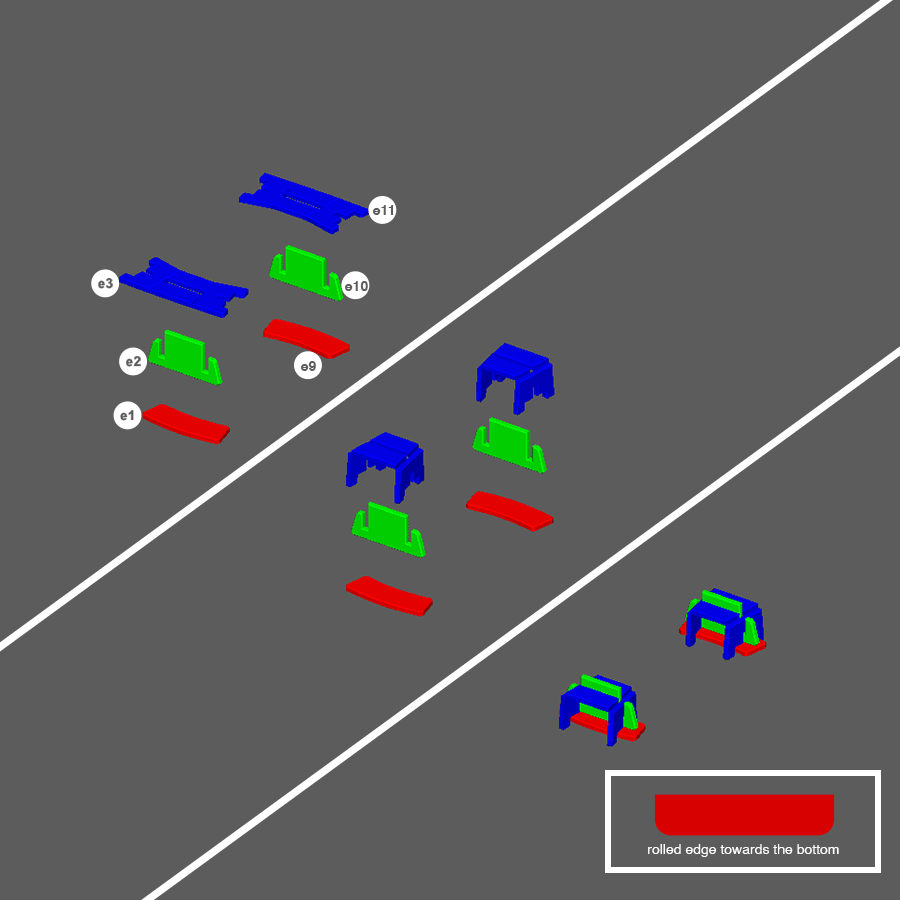
Step 15
- Glue and assemble pieces e1, e2, and e3 as shown to create one of the maglev assemblies.
- Glue and assemble pieces e9, e10, and e11 as shown to create one of the maglev assemblies.
Note: Make sure that pieces e1/e9 and e3/e11 match curve directions. The rolled edge of pieces e1/e9 should be facing down when assembled. See image inset for rolled edge example.
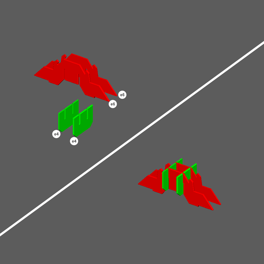
Step 16
- Glue and assemble both e4 and both e5 pieces as shown to make a support sub-assembly.
- Repeat one more time.
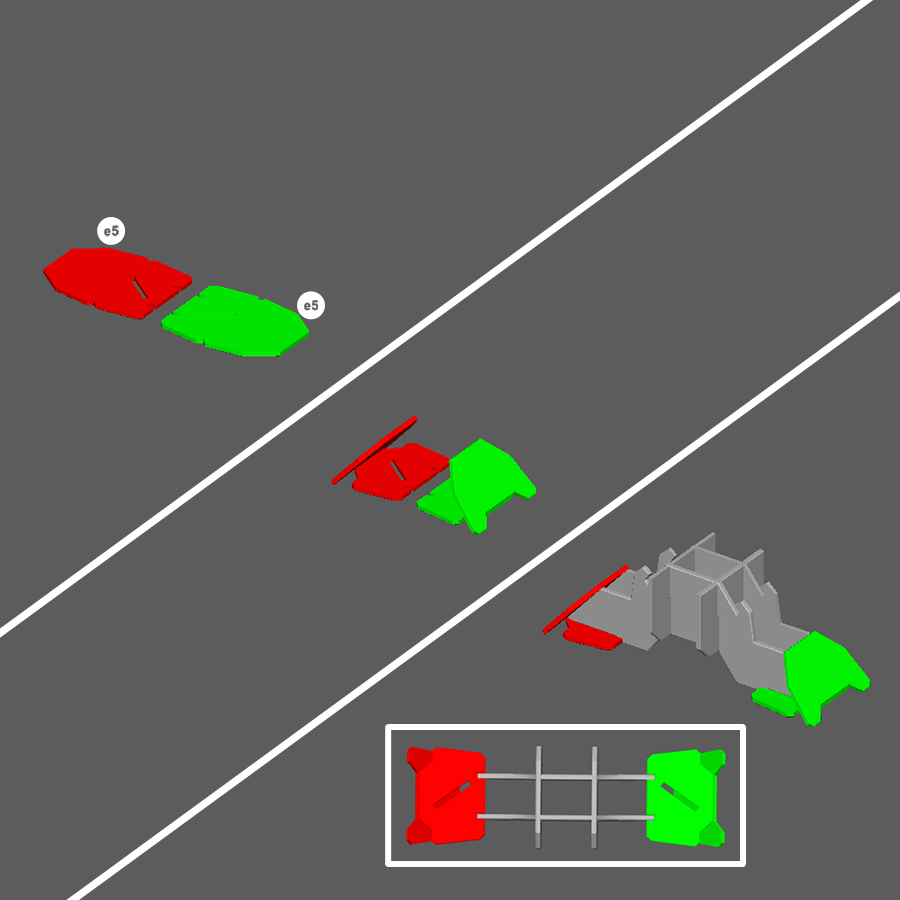
Step 17
- Glue both e5 pieces to the support sub-assemblies as shown.
- Repeat one more time to create the support assemblies.
Note: When finished the slots on the bottom of pieces e5 should face in different directions as shown in image inset.
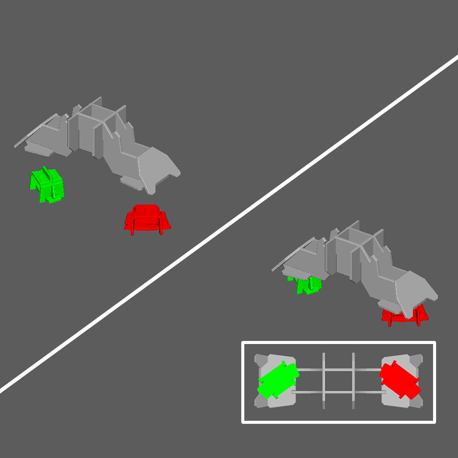
Step 18
- Glue both maglev assemblies to the support assemblies as shown.
Note: When finished the curve of the maglev assemblies should be oriented as shown in the image inset to fit the curve of the switch track.
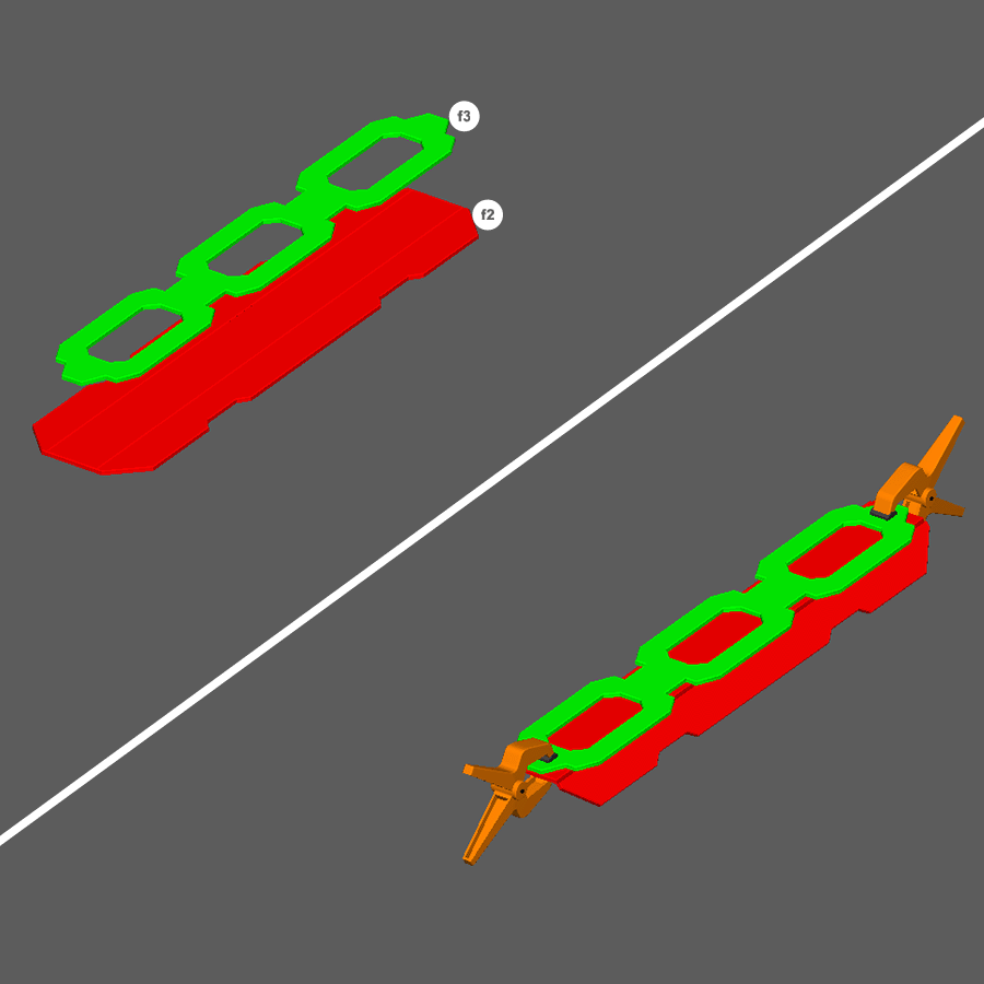
Step 19
- Glue and clamp f2 and f3 as shown to create the switch rail.
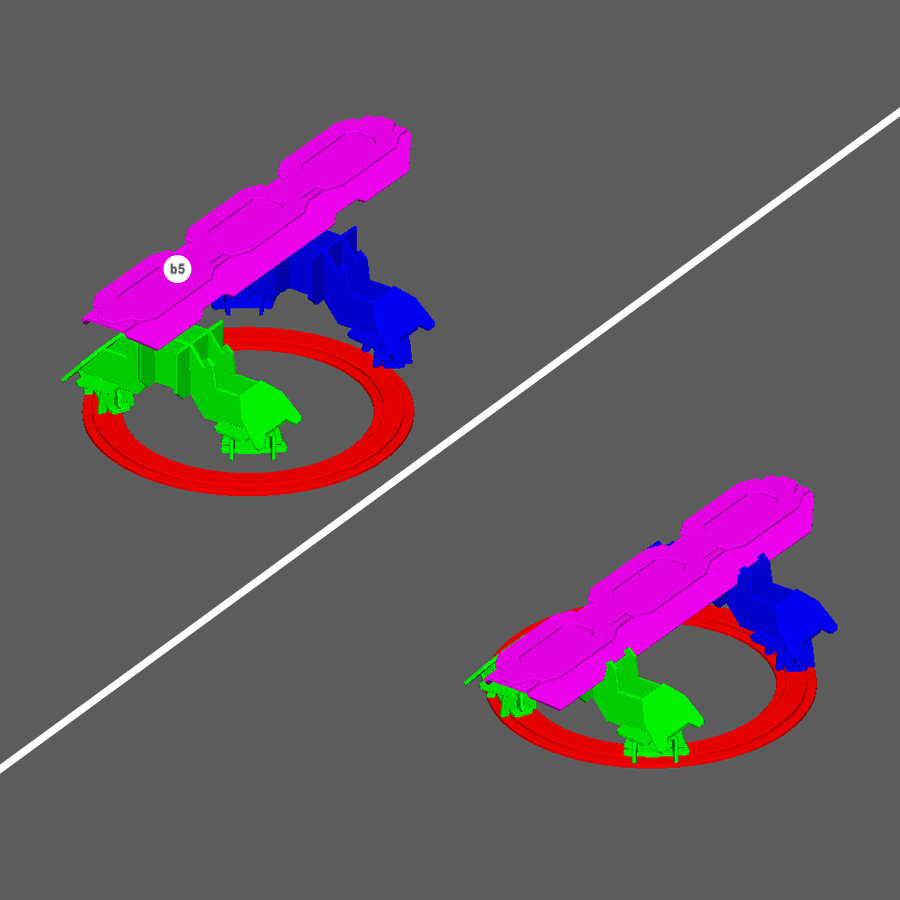
Step 20
- Assemble pieces as shown.
Note: Do Not Glue these pieces.
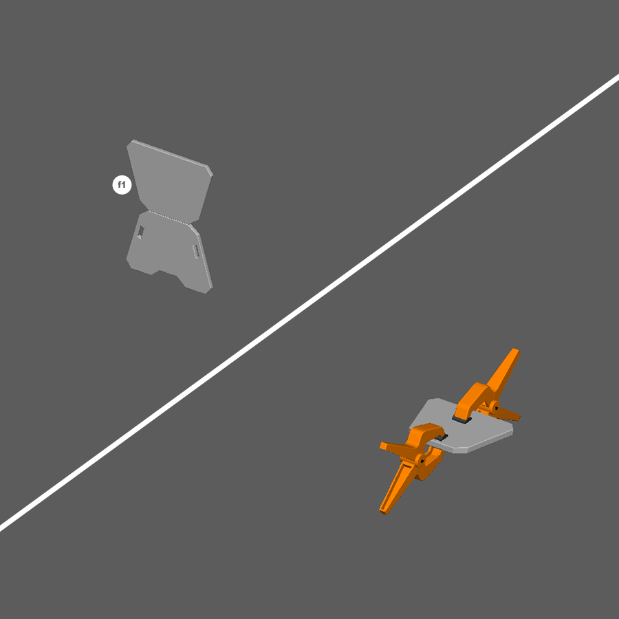
Step 21
- Glue and clamp piece f1 as shown.
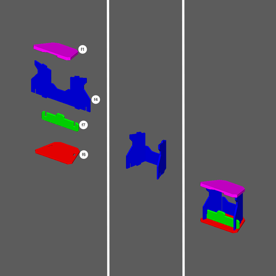
Step 22
- Fold and glue piece f4 to piece f7.
- Glue and assemble with pieces f1 and f6 as shown.
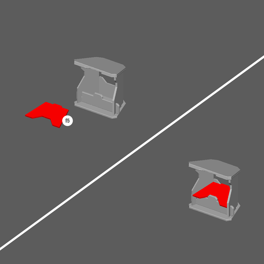
Step 23
- Piece f5 sits into place to create the switch control.
Note: Do not glue this part is reversable and can be used as an in game mechanic.
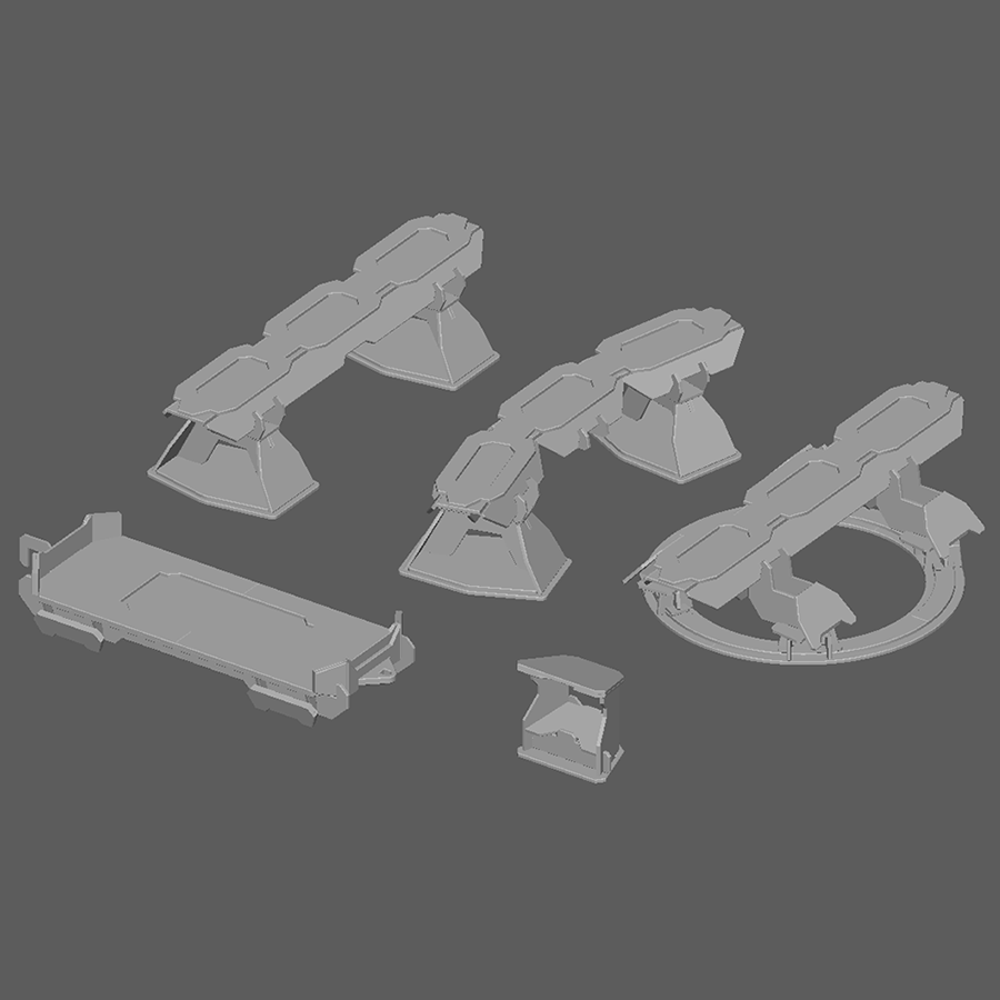
You’ve Finished The MagLev Rail Starter
Time to move on to another set!